8 minutes
Straightforward Top-Down Modeling in SolidWorks
NOTE (edited 01/30/26): While this post mostly talks about SolidWorks, the issues here are fundamental to parametric modeling and will apply to Fusion, FreeCAD, OnShape, or whatever other parametric modeling software you may be using may apply to other modeling software. Some programs, like Fusion, use top-down modeling as a fundamental paradigm, making these ideas somewhat unnecessary.
We’ve all been there - one dimension change, one edited mate, and your whole SolidWorks assembly comes crashing down in a wave of red error messages, broken mates, and failed rebuild sounds.
Anyone who works with large assemblies has to deal with this frequently. As well as you may think you know your assembly, you will inevitably forget about a mate or other constraint somewhere that prevents you from changing the dimension you need to change. SolidWorks doesn’t help you a lot with this; the dozens of broken mates that will often result from a change like that do not do a great job of pointing towards the actual root of the problem, the one mate that the over-constraint comes from.
The solution, as various websites and LLMs will point you to, is top-down modeling: a structured approach where each part is defined based on references to a single “skeleton” part that contains sketches and dimensions for your entire assembly.
The promise is simple; every dimension change, every stretch or shrink or movement, seamlessly updates all associated parts to the appropriate sizes since they’re all referencing the same part. In practice, however, modeling top-down ends up creating more problems than it solves.
Difficulties
Rebuild order
Some issues are simply limitations of SolidWorks itself.
Say you’ve built a box out of five individual plates. The base of the box has positions and dimensions defined by the skeleton, and the sides, for simplicity’s sake, are defined to be at the edges of the base piece, so they stretch depending on the position and size of that part.
This sounds great until you change the skeleton and SolidWorks decides to rebuild the sides first, so their positions are set at the old position of the base piece rather than the new position that the base should be at once SolidWorks gets around to rebuilding it.
Unfortunately, once SolidWorks tries to rebuild the base, it will notice that the mates with the sides no longer work and will fail the rebuild. This is a very simplistic scenario, one that SolidWorks in reality would likely handle fine, but the concept applies as you build larger and larger assemblies.
“Sticky” errors
SolidWorks doesn’t stop rebuilding once it runs across an error; it keeps rebuilding, attempting to find a stable state for the remaining parts. Therefore, when too many parts depend on other parts, a single part failing its rebuild cascades to every other part that has a relationship to that part, however indirect the relationship may be.
Sometimes, a feature or sketch gets pushed into a “sticky” invalid, unsolvable state, where even a reversion of the change can leave the feature completely broken. This happens frequently with sketches.
When a sketch has external references that move slightly too far, it can cross over itself or flip the direction of an essential dimension. When those changes create unsolvable geometry, SolidWorks can lock that sketch into place, keeping it from rebuilding properly regardless of the current state of the references.
Your only options at this point are either to go manually redraw and redefine the sketch or to force close your document without saving, potentially losing you a lot of the work you’ve put in.
Circular references
This has less to do with top-down modeling in particular and more to do with the general idea of using external references.
Often, when defining parts, you will accidentally make a part dependent on another part which is itself dependent on the first part. This is a circular reference, and SolidWorks is actually pretty good at catching it! Go to Performance Evaluation –> Rebuild Performance –> Circular Reference, and SolidWorks will give you a list of circular references and some tools to fix them.
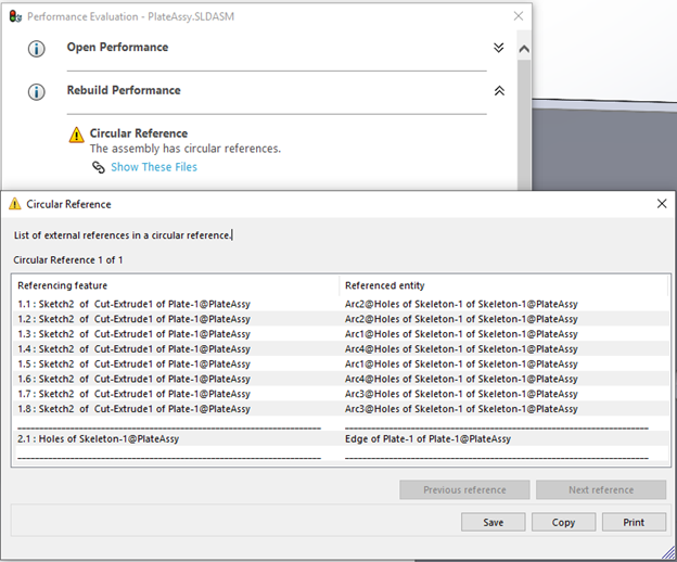
Unfortunately, when circular references extend through a chain of three or four parts before reaching back to the first one, SolidWorks has a much harder time catching them, and you’re going to have a much harder time fixing them.
Feature positioning
At an even more fundamental level, top-down modeling heavily limits how you may be used to building and editing assemblies.
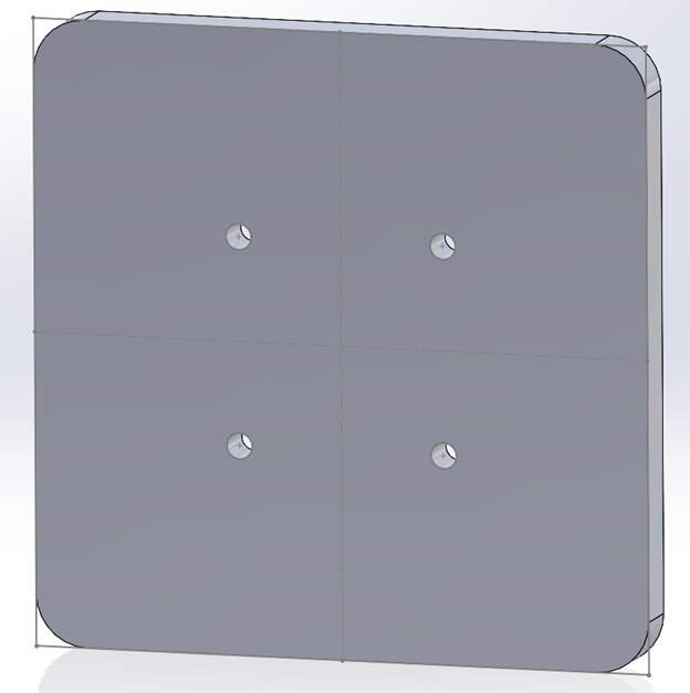
Imagine a scenario where you have an assembly with the skeleton and a plate with a number of bolts in it. The bolt holes could be defined a few different ways, but if you’re top-down modeling, your hole positions will likely be defined by the skeleton either directly with a Coincident sketch relation or semi-indirectly with a Convert Entities command, either of which would work fine with either an Extruded Cut or a Hole Wizard command.
Ideally, your skeleton part is mated to the origin for maximum stability, but this creates a serious problem. As soon as you move your plate to adjust its position in the assembly, your feature must stay in place relative to the origin, so the feature ends up in an unexpected position or perhaps fails entirely.
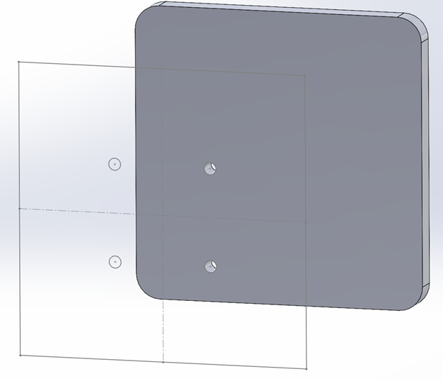
Theoretically, the solution to this is to make sure your parts are fully defined position-wise within the assembly before setting up features that may reference the skeleton, but now you can’t move your parts around or pull in a copy of those parts elsewhere in the assembly without putting in great effort to avoid breaking your in-context features. Because of this, the incredible ease of SolidWorks assemblies and mates goes away significantly under this form of top-down modeling.
A possible solution to this problem would be to get rid of all position-based relations and instead referencing dimensions of the skeleton part.
Unfortunately, that would mean manually mirroring much of the sketch structure from the skeleton for each part, which can be frustrating when you’ve already built those sketches in the skeleton.
Additionally, dimension-reference-based relations seem to be less reliable in even deep (Ctrl-Q) rebuilds, sometimes only resizing properly when you open the individual part file that contains the reference.
A Solution?
One of the best things about SolidWorks is its modularity. Each part can be built on its own, brought into an assembly, and assembled using a few intuitive mates. To bring this level of modularity to an assembly that needs the benefits of top-down modeling, a couple of modifications to the usual top-down modeling strategy are needed.
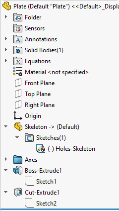
Instead of primarily using your skeleton in assemblies, first use it in the parts using derived parts.
For each part that must change based on dimensions of the skeleton part, open that individual part file, do Insert –> Part, and insert your skeleton part. Drag and drop as necessary to move the skeleton part to the top of the Feature Tree.
Edit 7/23/2025: Derived parts are not always an effective solution for this because SolidWorks will often “cache” part updates, causing failures down the line.
This is a SolidWorks problem, not a parametric modeling problem.
Instead, put each part into its own assembly with the skeleton part and use external references to define the part. Then, if necessary, use a tool like AutomateWorks or another SolidWorks API tool to automate opening and saving each subassembly to force SolidWorks to update the geometry.
If you’re using configurations of your skeleton part, API tools are also very helpful for changing the skeleton part configuration in each subassembly. Cascading configuration changes through assembly levels is not recommended.
All of the advice below continues to apply.
From there, reference and dimension things as you desire, making full use of Convert Entities and Coincident relations, because your part will now never move relative to the skeleton part, assuming you fix your part to the origin (as you always should regardless). Ideally, you should have no external references to anything but the skeleton part.
Then, when you bring parts into an assembly, change the skeleton part, and rebuild, each part will update itself, and no features will depend on part positioning since the referenced skeleton part is in the part file rather than at the assembly level. If you pushed something too far, only the part that got pushed too far will fail, and the breakage won’t cascade.
If you continue to use traditional mates, reliability will be approximately the same as in a bottom-up assembly. Misguided dimension changes will make the same mate errors as you would expect, but crucially, no parts should fail to rebuild, only mates. This makes errors much easier to track down.
To take it a step further, you could also make all your assembly mates relative to the skeleton part by using a combination of sketches and reference geometry. This is a little more work but will make your assembly practically error-proof, though with the potential downside of making interference and other impossible placements less obvious. If you aren’t using them already, this is when your Interference Detection and Section View tools come in. Add them to your toolbox! You won’t regret it, whether you take up this modeling strategy or not.
You don’t have to use this strategy exclusively. You can absolutely combine it with other external references and mates; your assembly reliability and flexibility will generally be inversely proportional to the number of other external references you have, but sometimes 80% reliability for 50% less development time is all you’re looking for.
Conclusion
I’ve had to learn this all the hard way over the last number of weeks, and I hope this helps you to avoid these issues. Use your tools; External References, Performance Evaluation, Interference Detection, Section View, and simply suppressing and unsuppressing parts can be invaluable for debugging assemblies. Good luck!